Simple Procedure
This example shows how to create, configure and use a procedure. Procedures can be represented as UML2 activity diagrams. The diagram for the procedure of this example is:
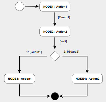
Hint: Model it with the free web-based modeling tool. The tool can be accessed from here.
The full code for this example can be downloaded from here as one single file which is ready to be compiled and linked with the C1 Implementation code (available from here).
A procedure is represented by its descriptor (the Procedure Descriptor or PRD). The PRD for the example procedure can be created as follows:
#define N_ANODES 4       /* The number of action nodes                  */
#define N_DNODES 1       /* The number of decision nodes                */
#define N_FLOWS 7        /* The number of control flows                 */
#define N_ACTIONS 2      /* The number of actions                       */
#define N_GUARDS 3       /* The number of control flow guards           */
FwPrDesc_t prDesc;       /* The procedure descriptor                    */

prDesc = FwPrCreate(N_ANODES, N_DNODES, N_FLOWS, N_ACTIONS, N_GUARDS);
The PRD is configured in three steps. In the first step, the action nodes are added to the PRD:
#define N1 1             /* The identifier of the first action node     */
#define N2 2             /* The identifier of the second action node    */
#define N3 3             /* The identifier of the third action node     */
#define N4 4             /* The identifier of the fourth action node    */

FwPrAddActionNode(prDesc, N1, &Action1);
FwPrAddActionNode(prDesc, N2, &Action2);
FwPrAddActionNode(prDesc, N3, &Action1);
FwPrAddActionNode(prDesc, N4, &Action2);
Here, Action1 is the pointer to the function which implements the action associated to nodes N1 and N2 and Action2 is the pointer to the function implementing the action associated to nodes N2 and N4.
In the second configuration step, the decision node is added to the PRD:
#define D1 1             /* The identifier of the decision node         */
#define N_OUT_OF_D1 2    /* The number of control flows out of D1       */

FwPrAddDecisionNode(prDesc, D1, N_OUT_OF_D1);
Finally, the control flows between the nodes are defined. Different functions must be used depending on the type of the source and destination of each control flow (for instance, FwPrAddFlowActToAct defines the control flow linking an action node to another action node; FwPrAddFlowActToFin defines the control flow linking an action node to the final node; etc). Here, Guard1, Guard2 and Guard3 are the pointers to the functions which implement the control flow guards.
FwPrAddFlowIniToAct(prDesc, N1, NULL);
FwPrAddFlowActToAct(prDesc, N1, N2, &Guard1);
FwPrAddFlowActToDec(prDesc, N2, D1, &Guard3);
FwPrAddFlowDecToAct(prDesc, D1, N3, &Guard1);
FwPrAddFlowDecToAct(prDesc, D1, N4, &Guard2);
FwPrAddFlowActToFin(prDesc, N3, NULL);
FwPrAddFlowActToFin(prDesc, N4, NULL);
The configuration process is now complete. Optionally, a user can ask a procedure to verify the completeness of its own configuration as follows:
if (FwPrCheck(prDesc) != prSuccess)
        printf("Procedure is not properly configured...\n");
After being configured, the procedure is ready to be executed. However, execution commands only have an effect on a procedure if the procedure has been started (a procedure can be started and stopped at any time: when it is stopped, it ignores execution commands). Thus, a commanding sequence for the procedure could be as follows:
FwPrStart(prDesc);
printf("Procedure is executed first time...\n");
FwPrExecute(prDesc);
printf("Procedure is executed second time...\n");
FwPrExecute(prDesc);
printf("Procedure is executed third time...\n");
FwPrExecute(prDesc);
printf("Procedure is executed fourth time...\n");
FwPrExecute(prDesc);
The pseudo-code above uses functions provided by the FW Profile. These functions must be included in the source code. For this example, the following files must be included:
#include "FwProfile/FwPrConstants.h"  /* Procedure Types and Constants     */
#include "FwProfile/FwPrDCreate.h"    /* Procedure Creation Functions      */
#include "FwProfile/FwPrConfig.h"     /* Procedure Configuration Functions */
#include "FwProfile/FwPrCore.h"       /* Procedure Execution Functions     */